以STM32Cubemx生成的一个简单程序来看,我们从main函数入手:
int main(void)
{
  /* USER CODE BEGIN 1 */

  /* USER CODE END 1 */

  /* MCU Configuration--------------------------------------------------------*/

  /* Reset of all peripherals, Initializes the Flash interface and the Systick. */
  HAL_Init();

  /* USER CODE BEGIN Init */

  /* USER CODE END Init */

  /* Configure the system clock */
  SystemClock_Config();

  /* USER CODE BEGIN SysInit */

  /* USER CODE END SysInit */

  /* Initialize all configured peripherals */
MX_GPIO_Init();MX_GPIO_Init()为GPIO初始化函数,我们跳转到它的定义看一下
void MX_GPIO_Init(void)
{

  GPIO_InitTypeDef GPIO_InitStruct = {0};

  /* GPIO Ports Clock Enable */
  __HAL_RCC_GPIOC_CLK_ENABLE();

  /*Configure GPIO pin Output Level */
  HAL_GPIO_WritePin(GPIOC, GPIO_PIN_13, GPIO_PIN_RESET);

  /*Configure GPIO pin : PC13 */
  GPIO_InitStruct.Pin = GPIO_PIN_13;
  GPIO_InitStruct.Mode = GPIO_MODE_OUTPUT_PP;
  GPIO_InitStruct.Pull = GPIO_NOPULL;
  GPIO_InitStruct.Speed = GPIO_SPEED_FREQ_LOW;
  HAL_GPIO_Init(GPIOC, &GPIO_InitStruct);

}可以看到GPIO使用一个名为GPIO_InitStruct的结构体进行配置,其内容为配置PC13口,设置为推挽输出模式,不启用上下拉电阻,输出速率设置为低,最后,通过HAL_GPIO_Init(GPIOC, &GPIO_InitStruct)函数完成配置,我们继续看这个函数
先来看第一个实参,GPIOC,我们转到其定义
#define GPIOC ((GPIO_TypeDef *)GPIOC_BASE)可以看到GPIOC是一个名为GPIOC_BASE,GPIO_TypeDef *类型的结构体指针,我们继续跟踪GPIOC_BASE,可以看到其定义
#define GPIOC_BASE (APB2PERIPH_BASE + 0x00001000UL)可以看到GPIOC_BASE的值为APB2PERIPH_BASE的值再加上0x00001000UL这个长整型地址,我们继续看APB2PERIPH_BASE
#define APB2PERIPH_BASE (PERIPH_BASE + 0x00010000UL)可以看到APB2PERIPH_BASE的值为PERIPH_BASE的值再加上0x00010000UL这个长整型地址,我们继续看PERIPH_BASE
#define PERIPH_BASE 0x40000000UL /*!< Peripheral base address in the alias region */可以看到PERIPH_BASE(外设基地址)的值为0x40000000UL,我们将三个地址的值相加,可得
GPIOC=0x4001 1000
查阅技术手册中的地址图
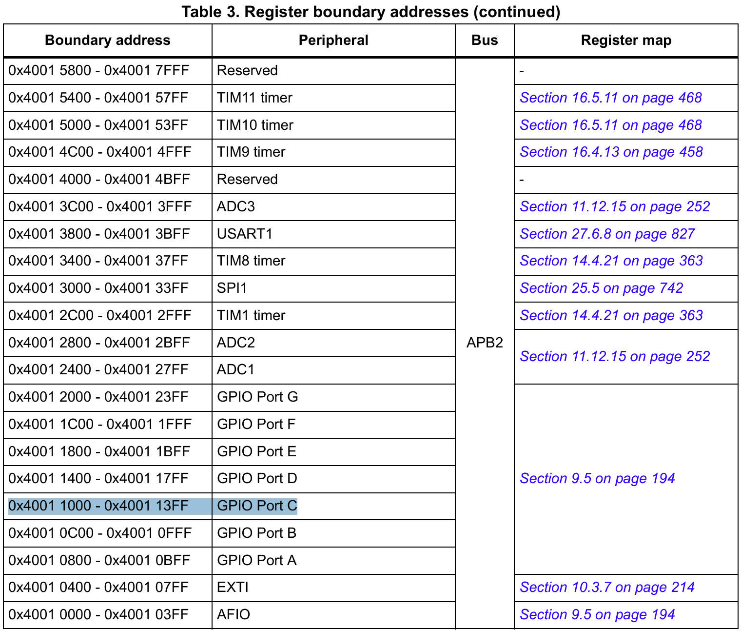
可以发现其正是GPIO PortC的起始地址,这样就搞清楚了,传入的第一个参数为GPIOC的起始地址
接下来我们转到HAL_GPIO_Init(GPIOC, &GPIO_InitStruct)这个函数,看看其是如何实现配置引脚功能的
/**
  * @brief  Initializes the GPIOx peripheral according to the specified parameters in the GPIO_Init.
  * @param  GPIOx: where x can be (A..G depending on device used) to select the GPIO peripheral
  * @param  GPIO_Init: pointer to a GPIO_InitTypeDef structure that contains
  *         the configuration information for the specified GPIO peripheral.
  * @retval None
  */
void HAL_GPIO_Init(GPIO_TypeDef  *GPIOx, GPIO_InitTypeDef *GPIO_Init)
{
  uint32_t position = 0x00u;
  uint32_t ioposition;
  uint32_t iocurrent;
  uint32_t temp;
  uint32_t config = 0x00u;
  __IO uint32_t *configregister; /* Store the address of CRL or CRH register based on pin number */
  uint32_t registeroffset;       /* offset used during computation of CNF and MODE bits placement inside CRL or CRH register */

  /* Check the parameters */
  assert_param(IS_GPIO_ALL_INSTANCE(GPIOx));
  assert_param(IS_GPIO_PIN(GPIO_Init->Pin));
  assert_param(IS_GPIO_MODE(GPIO_Init->Mode));

  /* Configure the port pins */
  while (((GPIO_Init->Pin) >> position) != 0x00u)
  {
    /* Get the IO position */
    ioposition = (0x01uL << position);

    /* Get the current IO position */
    iocurrent = (uint32_t)(GPIO_Init->Pin) & ioposition;

    if (iocurrent == ioposition)
    {
      /* Check the Alternate function parameters */
      assert_param(IS_GPIO_AF_INSTANCE(GPIOx));

      /* Based on the required mode, filling config variable with MODEy[1:0] and CNFy[3:2] corresponding bits */
      switch (GPIO_Init->Mode)
      {
        /* If we are configuring the pin in OUTPUT push-pull mode */
        case GPIO_MODE_OUTPUT_PP:
          /* Check the GPIO speed parameter */
          assert_param(IS_GPIO_SPEED(GPIO_Init->Speed));
          config = GPIO_Init->Speed + GPIO_CR_CNF_GP_OUTPUT_PP;
          break;

        /* If we are configuring the pin in OUTPUT open-drain mode */
        case GPIO_MODE_OUTPUT_OD:
          /* Check the GPIO speed parameter */
          assert_param(IS_GPIO_SPEED(GPIO_Init->Speed));
          config = GPIO_Init->Speed + GPIO_CR_CNF_GP_OUTPUT_OD;
          break;

        /* If we are configuring the pin in ALTERNATE FUNCTION push-pull mode */
        case GPIO_MODE_AF_PP:
          /* Check the GPIO speed parameter */
          assert_param(IS_GPIO_SPEED(GPIO_Init->Speed));
          config = GPIO_Init->Speed + GPIO_CR_CNF_AF_OUTPUT_PP;
          break;

        /* If we are configuring the pin in ALTERNATE FUNCTION open-drain mode */
        case GPIO_MODE_AF_OD:
          /* Check the GPIO speed parameter */
          assert_param(IS_GPIO_SPEED(GPIO_Init->Speed));
          config = GPIO_Init->Speed + GPIO_CR_CNF_AF_OUTPUT_OD;
          break;

        /* If we are configuring the pin in INPUT (also applicable to EVENT and IT mode) */
        case GPIO_MODE_INPUT:
        case GPIO_MODE_IT_RISING:
        case GPIO_MODE_IT_FALLING:
        case GPIO_MODE_IT_RISING_FALLING:
        case GPIO_MODE_EVT_RISING:
        case GPIO_MODE_EVT_FALLING:
        case GPIO_MODE_EVT_RISING_FALLING:
          /* Check the GPIO pull parameter */
          assert_param(IS_GPIO_PULL(GPIO_Init->Pull));
          if (GPIO_Init->Pull == GPIO_NOPULL)
          {
            config = GPIO_CR_MODE_INPUT + GPIO_CR_CNF_INPUT_FLOATING;
          }
          else if (GPIO_Init->Pull == GPIO_PULLUP)
          {
            config = GPIO_CR_MODE_INPUT + GPIO_CR_CNF_INPUT_PU_PD;

            /* Set the corresponding ODR bit */
            GPIOx->BSRR = ioposition;
          }
          else /* GPIO_PULLDOWN */
          {
            config = GPIO_CR_MODE_INPUT + GPIO_CR_CNF_INPUT_PU_PD;

            /* Reset the corresponding ODR bit */
            GPIOx->BRR = ioposition;
          }
          break;

        /* If we are configuring the pin in INPUT analog mode */
        case GPIO_MODE_ANALOG:
          config = GPIO_CR_MODE_INPUT + GPIO_CR_CNF_ANALOG;
          break;

        /* Parameters are checked with assert_param */
        default:
          break;
      }

      /* Check if the current bit belongs to first half or last half of the pin count number
       in order to address CRH or CRL register*/
      configregister = (iocurrent < GPIO_PIN_8) ? &GPIOx->CRL     : &GPIOx->CRH;
      registeroffset = (iocurrent < GPIO_PIN_8) ? (position << 2u) : ((position - 8u) << 2u);

      /* Apply the new configuration of the pin to the register */
      MODIFY_REG((*configregister), ((GPIO_CRL_MODE0 | GPIO_CRL_CNF0) << registeroffset), (config << registeroffset));

      /*--------------------- EXTI Mode Configuration ------------------------*/
      /* Configure the External Interrupt or event for the current IO */
      if ((GPIO_Init->Mode & EXTI_MODE) == EXTI_MODE)
      {
        /* Enable AFIO Clock */
        __HAL_RCC_AFIO_CLK_ENABLE();
        temp = AFIO->EXTICR[position >> 2u];
        CLEAR_BIT(temp, (0x0Fu) << (4u * (position & 0x03u)));
        SET_BIT(temp, (GPIO_GET_INDEX(GPIOx)) << (4u * (position & 0x03u)));
        AFIO->EXTICR[position >> 2u] = temp;


        /* Enable or disable the rising trigger */
        if ((GPIO_Init->Mode & RISING_EDGE) == RISING_EDGE)
        {
          SET_BIT(EXTI->RTSR, iocurrent);
        }
        else
        {
          CLEAR_BIT(EXTI->RTSR, iocurrent);
        }

        /* Enable or disable the falling trigger */
        if ((GPIO_Init->Mode & FALLING_EDGE) == FALLING_EDGE)
        {
          SET_BIT(EXTI->FTSR, iocurrent);
        }
        else
        {
          CLEAR_BIT(EXTI->FTSR, iocurrent);
        }

        /* Configure the event mask */
        if ((GPIO_Init->Mode & GPIO_MODE_EVT) == GPIO_MODE_EVT)
        {
          SET_BIT(EXTI->EMR, iocurrent);
        }
        else
        {
          CLEAR_BIT(EXTI->EMR, iocurrent);
        }

        /* Configure the interrupt mask */
        if ((GPIO_Init->Mode & GPIO_MODE_IT) == GPIO_MODE_IT)
        {
          SET_BIT(EXTI->IMR, iocurrent);
        }
        else
        {
          CLEAR_BIT(EXTI->IMR, iocurrent);
        }
      }
    }

	position++;
  }
}
由于整个代码比较复杂,我们重点关注如何设置输出模式,看其如何实现。对于输出引脚,由结构体成员GPIO_InitStruct.Mode进行设置,所以我们重点关注MODE关键字。
/* Based on the required mode, filling config variable with MODEy[1:0] and CNFy[3:2] corresponding bits */
      switch (GPIO_Init->Mode)
      {
        /* If we are configuring the pin in OUTPUT push-pull mode */
        case GPIO_MODE_OUTPUT_PP:
          /* Check the GPIO speed parameter */
          assert_param(IS_GPIO_SPEED(GPIO_Init->Speed));
          config = GPIO_Init->Speed + GPIO_CR_CNF_GP_OUTPUT_PP;
          break;
当MODE配置为推挽输出时,匹配到了这段代码,我们重点注意config如何写入寄存器
/* Check if the current bit belongs to first half or last half of the pin count number
       in order to address CRH or CRL register*/
      configregister = (iocurrent < GPIO_PIN_8) ? &GPIOx->CRL     : &GPIOx->CRH;
      registeroffset = (iocurrent < GPIO_PIN_8) ? (position << 2u) : ((position - 8u) << 2u);

      /* Apply the new configuration of the pin to the register */
MODIFY_REG((*configregister), ((GPIO_CRL_MODE0 | GPIO_CRL_CNF0) << registeroffset), (config << registeroffset));可以看到由(iocurrent < GPIO_PIN_8) ? &GPIOx->CRL : &GPIOx->CRH;判断出了要操作的是高还是低寄存器,即操作GPIOC_CRH寄存器,MODIFY_REG应该是写入操作,我们看一下其定义
#define MODIFY_REG(REG, CLEARMASK, SETMASK) WRITE_REG((REG), (((READ_REG(REG)) & (~(CLEARMASK))) | (SETMASK)))可以发现MODIFY_REG先是通过WRITE_REG((REG)读出寄存器的值,在(READ_REG(REG)) & (~(CLEARMASK)中用掩码清除掉特定位的值,再使用(SETMASK)掩码来置位。
再回到GPIO初始化函数MX_GPIO_Init()中,在配置引脚输出模式之前,还执行了一个函数
HAL_GPIO_WritePin(GPIOC, GPIO_PIN_13, GPIO_PIN_RESET);通过查看其定义,可以看到这个函数是通过GPIOx_BSRR(端口位设置/清除寄存器)写入输出数据寄存器
GPIOx_ODR来配置输出的高低电平,这样一但输出模式配置完成,就能够直接输出高/低电平。
/**
  * @brief  Sets or clears the selected data port bit.
  *
  * @note   This function uses GPIOx_BSRR register to allow atomic read/modify
  *         accesses. In this way, there is no risk of an IRQ occurring between
  *         the read and the modify access.
  *
  * @param  GPIOx: where x can be (A..G depending on device used) to select the GPIO peripheral
  * @param  GPIO_Pin: specifies the port bit to be written.
  *          This parameter can be one of GPIO_PIN_x where x can be (0..15).
  * @param  PinState: specifies the value to be written to the selected bit.
  *          This parameter can be one of the GPIO_PinState enum values:
  *            @arg GPIO_PIN_RESET: to clear the port pin
  *            @arg GPIO_PIN_SET: to set the port pin
  * @retval None
  */
void HAL_GPIO_WritePin(GPIO_TypeDef *GPIOx, uint16_t GPIO_Pin, GPIO_PinState PinState)
{
  /* Check the parameters */
  assert_param(IS_GPIO_PIN(GPIO_Pin));
  assert_param(IS_GPIO_PIN_ACTION(PinState));

  if (PinState != GPIO_PIN_RESET)
  {
    GPIOx->BSRR = GPIO_Pin;
  }
  else
  {
    GPIOx->BSRR = (uint32_t)GPIO_Pin << 16u;
  }
}